 Subtraction Solids
As the name implies, subtraction solids are intended for subtraction from other solids using Boolean operations. ‘Cube’ and ‘Plane’ are provided as standard subtraction solids in the toolbar of the 3D Construction plug-in, and further, it is possible to convert existing 3D constructions to subtraction solids. This function is available over the context menu when a 3D construction is selected.

The above-mentioned subtraction solids are generally valid globally for the entire project and all its components. These subtraction solids are not intended for use in modeling. For modeling, other mechanisms such a Boolean operations are provided.
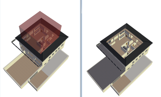
An example, the ‘Cube’ subtraction solid in a building:

In the example shown the cube was subtracted from all layers of the building. In the view on the left the cube is still visible, while on the right it is set as invisible in the visibilities dialog. The cut-out representation, however, has no effect on the 2D representation in the plan view.
Tip: Processing for such operations is very complex, and depending on the project can take several minutes. Before creating such views the project should first be saved, as depending on the system the available main memory is also an important factor.
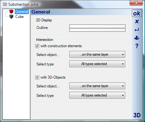
The scope of the subtraction can be set in the properties dialog for a subtraction solid. Here can be specified which types of construction element and which layers are to be affected by the subtraction solid.

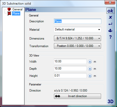
Planes remove elements dependant on the direction in which they are input, i.e. to the right of their direction of input. Therefore, the direction of input of a plane can be subsequently changed using the ‘Invert direction’ button in the dialog, or over the context menu.

An example with the direction of input reversed:

More:
 Converting 3D Constructions to Subtraction Solids
 Examples of the Use of Subtraction Solids
 Example of a Subtraction Solid in the Terrain
 Example of a Subtraction Solid in Roofs