 Contour / Path , Example for a Drainpipe
First, we define the contour of the drainpipe in a cross-section view using 2D elements from the 2D Graphics plug-in, i.e. lines and arcs. It is important that the end points of the 2D elements meet, as otherwise a contour or path cannot be created. The following example shows the contour made up of two lines and two arcs (input with 3 points). On input, the number of segments for the arcs was set to 6, see the chapter ‘Performance, Number of Segments’.

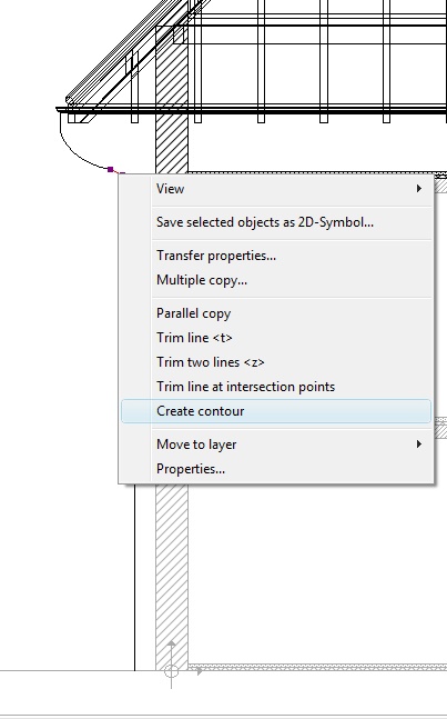
Now select one of the 2D elements and click on ‘Create contour’ in the context menu.

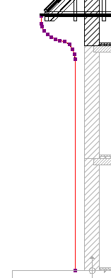
The resultant contour:

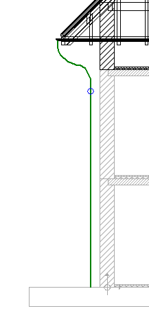
Next we choose ‘Contour / Path’ ![]() as input option for the sweep solid and position the cursor over the contour, which is highlighted in green as soon as it is detected.
as input option for the sweep solid and position the cursor over the contour, which is highlighted in green as soon as it is detected.

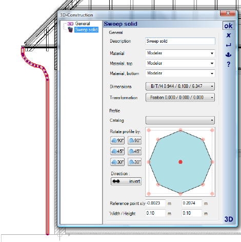
A left mouse-click completes the input and creates the sweep solid. Finally, a suitable profile for the drainpipe can be selected and modified in the properties dialog.
