Exterior Walls
Select from the ‘Plug-in toolbar’ (the third horizontal toolbar) with the button for ‘Building components’  the corresponding plug-in. The functions for building components are then shown in the left-hand vertical toolbar (the plug-in functions are situated below the general functions – these are functions that are always available, e.g Guidelines, Text etc.). The top button of the building components is for the function ‘Walls’.

Then activate ‘exterior wall’ with a left mouse click on the button. Buttons offering various insert options are displayed in the second vertical toolbar. Now select the multiple tool ‘Between two points’. A right click in the planning area opens the following context menu.

Now click on the ‘Properties’ menu item, which opens the ‘Wall properties’ dialog.

For now we leave the settings as shown in the illustration and close the dialog with ‘OK’. Now set the start point of the first wall to a point on the grid. The wall snaps to the start point along its axis and is attached to the cursor so that it can be positioned. With the key combination ‘Ctrl+W’ the reference point of the wall at the start point can be changed – from axis to inside edge, to outside edge, to axis.

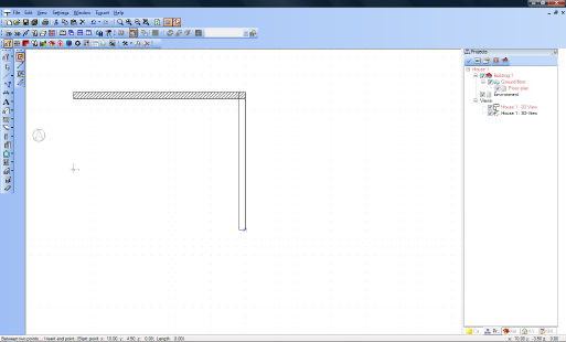
We select the outside edge as the reference point. Drag out the wall horizontally to the right with the mouse and notice how the value for its length changes in the status bar. Drop the wall at 10.00 m with a left mouse-click.

Now drag out the next wall vertically downwards to a length of 8.00 m.

Extend the next wall horizontally 10.00 m to the left and then back to the start point. When the final click is made, and the polygon that forms the contour of the walls is closed, a name for the room appears in the plan. The insert wall function is terminated by pressing the ‘Esc’ key. This should now result in the following picture.

You can check the progress of your work once more in a 3D view, by for example clicking on ‘New 3D view’.

As you can see the room is already provided with a floor, and the recess to support the ceiling is also visible. However ceilings are automatically removed using the visibility settings so that you can see into the structure.
Switch back to the 2D view. If you left click in the room it is highlighted in red to show that it has been selected.. By choosing ‘Properties’ from the context menu, which is opened with a right mouse-click, the ‘Room’ dialog appears.

In the ‘Room’ dialog you can edit the room as regards text, calculation of area, and floor structure.